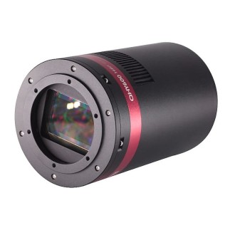
Camera MoravianMonochrome C1-3000A CMOS Sony IMX265 sensor
The C1 camera models are equipped with CMOS detectors ofglobal shutterSony IMX with 3.45 × 3.45 μm square pixels.The individual models differ only in resolution.
All sensors used utilize a global electronic shutter.This means that each pixel within the image is exposed at the same time, unlike rolling shutter sensors, which expose individual lines one after the other.There is no difference for long exposures of static objects, but imaging moving objects using a short exposure time with the rolling shutter leads to distortions in the image shape.
Two C1 camera lines are available depending on the available dynamic range (bit depth of the digitized pixels):
-
C1 cameras with Sony IMX sensors compatible with 8-bit and 12-bit digitization.Because each 12-bit pixel occupies two bytes when transferred to the host PC, the download time of the 12-bit image is longer compared to the 8-bit image.The maximum FPS in 8-bit mode is significantly higher.
-
C1 cameras with Sony IMX sensors that only support 12-bit digitization.As the 12-bit readout mode is always used for long exposure applications (astronomical photography, scientific research) anyway, the shorter theoretical download time in 8-bit mode presents no limitations for real-world scenarios.All other parameters being equal (sensor size, resolution, pixel size, noise, etc.), the lower price of these cameras can be very attractive.
C1 camera models with 8-bit and 12-bit digitization:
| Model |
cMOS sensors |
Resolution |
Pixel size |
Image area |
| C1-1500 |
IMX273 |
1456 × 1088 pixels |
3.45 × 3.45 microns |
5.02 × 3.75 mm |
| C1-3000 |
IMX252 |
2064 × 1544 pixels |
3.45 × 3.45 microns |
7.12 × 5.33 mm |
| C1-5000 |
IMX250 |
2464 × 2056 pixels |
3.45 × 3.45 microns |
8.50 × 7.09 mm |
| C1-12000 |
IMX253 |
4112 × 3008 pixels |
3.45 × 3.45 microns |
14.19 × 10.38 mm |
Only C1 camera models with 12-bit digitization:
| Model |
cMOS sensors |
Resolution |
Pixel size |
Image area |
| C1-3000A |
IMX265 |
2064 × 1544 pixels |
3.45 × 3.45 microns |
7.12 × 5.33 mm |
| C1-5000A |
IMX264 |
2464 × 2056 pixels |
3.45 × 3.45 microns |
8.50 × 7.09 mm |
| C1-12000A |
IMX304 |
4112 × 3008 pixels |
3.45 × 3.45 microns |
14.19 × 10.38 mm |
The C1 cameras are designed to work in cooperation with a host personal computer (PC).Unlike digital still cameras, which run independently on the computer, scientific cameras generally require a computer for operation control, image downloading, processing, and storage, etc. To operate the camera, you need a computer that:
-
It is compatible with a PC standard and runs a modern Windows 32-bit or 64-bit operating system.
-
It is compatible with a standard PC and runs a 32-bit or 64-bit Linux operating system.
-
Support for x64-based Apple Macintosh computers is also included.
The C1 cameras are designed to connect to the host PC via the USB 3.0 interface, operating at 5 Gbps.The cameras also support the USB 2.0 port to communicate with a host PC.
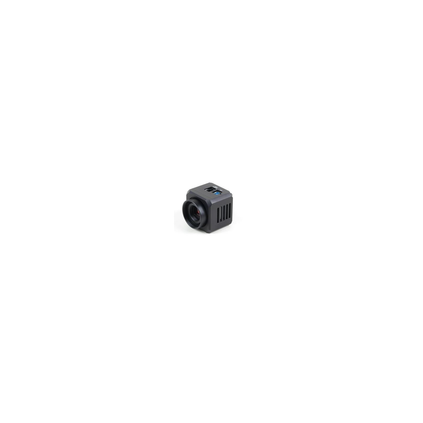
Alternatively, it is possible to use thedeviceethernet camera adapter Moravian .This device can connect up to four Cx (with CMOS sensors) or Gx (with CCD sensors) cameras of any type and offers a 1 Gbps and 10/100 Mbps Ethernet interface for direct connection to the host PC.Since the PC then uses the TCP/IP protocol to communicate with the cameras, it is possible to insert a WiFi adapter or other network device into the communication path.
C1 camera system
Components of the C1 camera system include:
-
C1 camera head with CS mount adapter
-
C1 camera head with combined T-thread (M42×0.75) and CS-mount adapter
-
C/CS mount to 1.25" cylinder adapter
-
Short (10 mm) C/CS mount variant for 1.25" cylinder adapter, designed for use with OAG
-
Off-axis guide adapter (OAG) to large refrigerated chamber (C2/C3/C4 or G2/G3/G4)
-
Extension tube with M48 × 0.75 thread and 55 mm rear focal length
-
Extension tube with M42 × 0.75 thread and 55 mm rear focal length (standard T-thread adapter)
-
Adapter for Canon EOS bayonet lens
-
Nikon bayonet lens adapter
The main function of the CMOS camera electronics, besides sensor initialization and some auxiliary functions, is to transfer data from the CMOS detector to the host PC for storage and processing.Therefore, unlike CCD cameras, the design of the CMOS camera cannot influence the number of important camera characteristics, such as the dynamic range (bit depth of the digitized pixels).
The sensors used in the C1 cameras show very good linearity in response to light.This means that the camera can also be used for entry-level research projects, such as photometry or brighter variable stars, etc.
 respuesta a la luz")
C1-3000 (IMX252) light response
As already noted, there are two lines of the C1 camera series, which differ in the sensor used.The first series offers four different reading modes:
-
8-bit slow modeWith a scanning speed of ~132 MPx/s
-
12-bit slow modeWith a scanning speed of ~72 MPx/s
-
8-bit fast modeWith a digitizing speed of ~263 MPx/s
-
12-bit fast modeWith a scanning speed of ~132 MPx/s
The "A" version of the C1 cameras offers only a single reading mode:
The above mentioned scanning speeds are valid for USB 3.0 connection.Also note that scanning speeds do not necessarily lead to corresponding FPS, as each downloaded image must be processed and displayed, which is also time consuming.This time is negligible, if the slow scan camera needs many seconds to download the image, but in the case of fast CMOS cameras, the image processing time on the PC (e.g. calculation of the image standard deviation, etc.) may be longer than downloading the image itself .
The sensors used in the C1 cameras offer a programmable gain from 0 to 24 dB, which translates into the multiplication of the output signal from 1× to 15.9×.The gain can be set with a 0.1 dB step.
Conversion factors and read noise
Generally, many sensor characteristics depend on the gain used.Therefore, we provide two parameter lists for minimum and maximum gain.
| Digitizing resolution |
12 bits |
12 bits |
8 bits |
8 bits |
| Sensor gain |
0dB |
24dB |
0dB |
24dB |
| Total well capacity |
11000 e- |
1100 e- |
2600 e- |
1100 e- |
| Conversion factor |
2.8 e-/ADU |
0.3 e-/ADU |
10.0 e-/ADU |
4.4 e-/ADU |
| Read noise |
2.2 e-RMS |
2.0 e-RMS |
4.2 e-RMS |
9.7e-RMS |
Observation:
Please note that the above values are not published by the sensor manufacturer, but are determined from images acquired with the SIPS software package.Results may vary slightly depending on the test run, the particular sensor and other factors (e.g. sensor temperature, sensor illumination conditions, etc.), but also depending on the software used to determine these values, as the method is based on statistical analysis of the sensor. light response.
C1 cameras are capable of very short exposures.The shortest exposure time is 125 μs (1/8000 of a second).This is also the step by which the exposure time is expressed.Then, the second shortest exposure is 250 μs, etc.
The host PC controls the extended exposure time and there is no upper limit on the exposure time.In reality, longer exposures are limited by sensor saturation, either by incoming light or dark current (see next subchapter).
Dark current is an inherent characteristic of all silicon circuits.It is called "dark" because it is generated regardless of whether the sensor is exposed to light or not.The dark current, injected into individual pixels, appears in the image as noise.The higher the exposure, the more noise is present in each image.As it is generated by the random motion of particles, it depends exponentially on temperature (that is why the noise generated by the dark current is also called "thermal noise").Generally, lowering the sensor temperature by 6 or 7 °C reduces the dark current by half.
Although the C1 chambers are not equipped with active thermoelectric cooling (Peltier), they are still equipped with a small fan that exchanges air inside the chamber body.In addition, a small heat sink is located directly on the sensor (with the exception of the C1-1500 model, whose sensor is too small for the heat sink) to remove as much heat as possible.Therefore, sensor C1 cannot be cooled below ambient temperature, but its temperature is kept as close as possible to ambient.Compared to closed designs, the sensor temperature in the C1 chamber can be up to 10 °C lower and the resulting dark current can be less than half.
, mientras que las rejillas de ventilación de salida están en el lado opuesto (imagen de la derecha)")
The cooling air inlet is on the left side of the chamber (left image), while the exhaust vents are on the opposite side (right image)
Fan operation can be controlled from the software.SIPS directly offers a slider control fan in the "Cooling" tab of the main window of the camera control tool.Camera drivers for other software must rely on the driver's configuration dialog box to control the fan.

With the fan off, the sensor temperature rises rapidly more than 10 °C above the ambient temperature.When the fan is turned on, the temperature drops by 5 °C or more.
Many astronomical telescope mounts (especially mass-produced ones) are not accurate enough to maintain perfectly round star images over long exposures without small corrections.Cooled astronomical cameras and digital SLR cameras allow perfectly sharp, high-resolution images, so that even a small irregularity in the mount tracking appears as deformation of the stellar image.The C1 cameras were specially designed with automatic mounting guidance in mind.
The C1 cameras were designed to operate without mechanical moving parts (with the exception of the magnetically levitating fan).The electronic shutter allows extremely short exposures and also to obtain thousands of images in a short time, which is necessary for quality guidance.
C1 cameras work in connection with a host computer (PC).Guidance corrections are not calculated in the camera itself, it only sends the acquired images to the PC.The software running on the PC calculates the required state difference and sends the appropriate corrections to the telescope mount.The upside of using a host PC CPU to process images is the fact that today's PCs provide overwhelming computational power compared to any embedded processor inside the camera guide.Guidance algorithms can determine the star position with sub-pixel accuracy, can match multiple stars to calculate the average difference, which limits view effects, etc.
Calculated corrections can be sent back to the mount via the PC to mount link.If the mounting controller does not support the so-called "Pulse Guide" commands, it is possible to use the "Autoguider" port.Simply connect the C1 camera and the mount using a standard 6-wire cable and guide the mount through the camera.
The maximum sink current of each pin of chamber C1 is 400 mA.If the mount does not treat the autoguider port only as a logic input, but switches the guiding motors directly by these signals, a relay box must be inserted between the camera and the mount.The relay box ensures the switching of the currents required by the mount.

The standard 6-pin Autoguider port is located next to the USB3 port on the top of the C1 camera
The Autoguider port follows the de facto standard introduced by the SBIG ST-4 autoguider.The pins have the following functions:
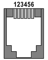 |
| 1 |
AR + (Right) |
|
Dec + (Top) |
|
Dec - (Bottom) |
|
AR - (Left) |
| 5 |
Common land) |
|
Not connected |
|
Mechanical specifications
The C1 camera head is designed to be lightweight and compact for easy attachment to even small spotting scopes or spotting scopes.The compact and robust camera head measures only 57 × 57 × 48 mm excluding lens adapter.
The head is CNC machined from high quality aluminum and anodized black.The header itself contains a USB-B 3.0 (device) connector and a standard 6-pin "autoguide" connector.
| Internal mechanical seal |
No |
| Shorter exposure time |
125 μs |
| Longer exposure time |
Limited only by chip saturation |
| Head dimensions |
57 mm × 57 mm × 48 mm (without lens adapter) |
| Rear focal length |
12.5 mm for 1/32 UN thread (compatible with CS mounting) |
|
18.5 mm for M42 × 0.75 thread (T-mount) |
| Camera head weight |
215 grams |
C1 cameras are supplied with two types of telescope/lens adapters:
-
Adapter with 1/32 UN thread and 12.5 mm rear focal length (CS mount).
-
Adapter with M42 × 0.75 thread (T-thread) and 18.5 mm rear focal length.This adapter also contains 1/32 UN internal thread with 12.5 mm BFD (CS mount).
 (izquierda) y con adaptador de montura CS (derecha)")
C1 camera with T-thread adapter (M42 × 0.75) (left) and with CS-mount adapter (right)
CS-mount is compatible with a wide range of CCTV lenses.If a C-mount lens (with a rear focal length of 17.5 mm) is to be used, a simple 5 mm thick adapter ring can be used.
Warning:
If the C1 camera is to be used with OAG for refrigerated Cx or Gx cameras, a 10 mm C to 1.25" short barrel adapter must be used.This adapter, shipped with the respective OAG, is fully compatible with the C1 camera.
Please note that the C1 camera with M42 × 0.75 adapter (T-thread) cannot be used with OAG, although the short barrel adapter CS at 1.25" can be attached to it. The large diameter M42 adapter interferes with the screws securing the camera to the OAG guide port. For this reason, the C1 variant is still supplied with only CS mount adapter.
The C to 1.25" cylinder adapter, compatible with standard 1.25" eyepieces, is included in the camera package.Therefore, the C1 camera can be easily mounted on virtually all astronomical telescopes in place of an eyepiece.
The T-mount interface (also known as T-thread adapter) is defined by the M42 × 0.75 thread dimensions as well as the 55 mm rear focal length.The T-thread adapter for C1 cameras does not meet the second parameter, its BFD is only 18.5 mm.The 55 mm BFD is not necessary in all applications and maintaining a relatively large BFD would make the adapter quite bulky.
However, an extension tube with male thread M42 × 0.75 is available.This extension tube converts the BFD of the C1 camera to 55 mm, required by numerous focal reducers, field flatteners, coma correctors and other optical elements.
Two variants of the 55 mm BFD extension tubes are available:
, tubo de extensión BFD de 55 mm con rosca M42 × 0,75 (centro) y con rosca M48 × 0,75 (derecha)")
C1 camera (left), 55 mm BFD extension tube with M42 × 0.75 thread (center) and with M48 × 0.75 thread (right)
In addition, extension tubes with bayonet interfaces for standard photographic lenses are available:
Insinuation:
The outer diameter of the extension tube is exactly 2 inches (50.8 mm), so it can allow the use of the C1 camera with any 2" focuser instead of a 2" eyepiece.

C1 camera with attached Canon EOS lens
Tripod and metric threads

The bottom of the C1 camera contains a standard 0.25" (tripod) thread and 4 metric M3 threaded holes
If the C1 camera is not attached to the telescope focuser via its telescope/lens adapter, it can be attached to a standard photographic tripod using a 0.25" thread.Another possibility is to use 4 metric M3 threaded holes, also located at the bottom of the camera head.

Position of the four M3 threaded holes on the bottom of the camera head C1
Front view dimensions of the C1 camera head with CS mount adapter (left) and side view dimensions and rear focal length (right)
Camera head C1 with M42 × 0.75 adapter front view dimensions (left) and side view dimensions and rear focal length (right)
Software and driver support for the Cx series CMOS cameras is as broad as for their siblings with Gx series CCD cameras.
However, the latest versions of all software packages and drivers must be installed to use the Cx cameras.
-
If the C1 camera is connected directly to the host PC via a USB cable, a new CxCamera.sys system driver must be installed (see the "Installing and Using Drivers and Software" manual, which is shipped with each camera).Thesystem driver pre-installation package version 2.3And later contains this driver.
-
When the C1 camera is connected through the camera Ethernet adapter device Moravian, if the device must be upgraded to thefirmware version 42Or later to work with CMOS cameras (see the "Camera Ethernet Adapter User Guide") Moravian" for the firmware update procedure).
Insinuation:
When the SIPS is connected to the camera via the camera Ethernet adapter device from Moravian, the firmware version of the attached device is displayed in the notification area of the Windows Action Center.
-
Linux driver packages and libraries must also be updated to the latest versions.See the Downloads section of this site for more details.
The software packageSIPS(Scientific Image Processing System)version 3.16Or later is required to control the C1 cameras.
Warning:
Support for CMOS-based Cx cameras was gradually added to the single SIPS version.While earlier versions of SIPS minors may recognize C1 cameras, always use v3.16 or later for reliable camera operation.
C1 camera controllers forpackagesThird-party software must also be upgraded to work with C1 cameras.The minimum versions for the respective drivers are:
-
ControllersASCOMversion 4.10
-
Controllers forTheSkyX(all versions for Windows, MacOS and Linux)version 2.2
-
ControllersAstroartversion 3.2
Powerful softwareSIPS(Scientific Image Processing System), supplied with the camera, allows complete control of the camera (exposures, cooling, filter selection, etc.).Automatic image sequences with different filters, different binning, etc. are also supported.With full compatibility with the ASCOM standard, SIPS can also be used to control other observation equipment.Specifically telescope mounts, but also other devices (focusers, dome or roof controllers, GPS receivers, etc.).
SIPS also supports automatic guidance, including image screening.Both "autoguider" port hardware interface (6-wire cable) and "Pulse-Guide API" mounting guide methods are supported.For high quality mounts, capable of tracking without the need to guide at the end during an exposure, only guidance between images using the main camera is available.
")
SIPS controlling the entire observatory (shown in optional dark skin)
But SIPS is capable of much more than just controlling the camera and observatory.Many tools are available for image calibration, handling of 16-bit and 32-bit FITS files, image set processing (e.g., median combination), image transformation, image export, etc.